Origins
The same style of manual steer rack & pinion was used in all big sedans (T2000/T2500), TR4-6, Spitfire & GT6. Early TR4 & Herald racks used a unique solid alloy chassis mount, but are otherwise the same basic design as later units. The 1300FWD, Dolomite & Toledo ranges used the same style of rack shaft but a different housing & pinion because of its angular mounting in the car. The TR7 rack is different again & is not discussed in this article
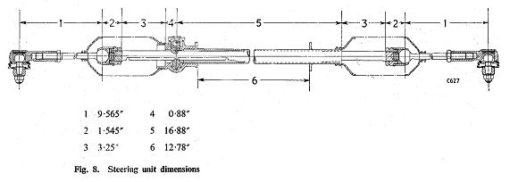
 In all cases, Triumph racks were made in both LHD & RHD formats, with the only difference being the handing of the casing & the pinion gear tooth angle—the rack shaft & tie rods remaining the same. With the exception of the Dolomites, 6 & 7 tooth pinions can be freely exchanged to give a quicker or slower rack as required. The 7-tooth (spitfire/TR) pinion is commonly found in race saloons.
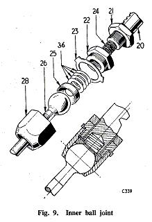
Adler & Alford made most (if not all) of the racks for Triumph production, & also made derivatives for kit car makers & specialists like Lotus, TVR, Bond etc, & even for in-house tuning group, Leyland S-T for their Dolomite rally/race cars. These all occasionally turn up as standard Triumph spares and can be the source of steering problems. British Leyland also used the “Triumph” rack in the MG1500 Midget, but with thicker lock stops & a unique (5/8” splined) pinion to suit the Midget steering column. Many of the “specials” used unique length tie rods (part no 26 in picture) & different thickness lock-stops (part no 21 in picture). Triumph also changed the lock stops from model-to-model & there was even some interchangeability in this part between manual & power steer in Saloon/Stags. The lock to lock varies between 4.25 and 3.25 turns depending on the rack shaft length, pinion teeth and lock stop thickness. The ball socket (no.25 in picture above) was made in both steel & nylon. The table below shows some key data for each common application.
|
Model
|
Rack shaft part #
|
Rack length (mm) Note 2
|
Tie Rod part #
|
Tie rod length (mm) Note 1
|
Pinion part # (right-hand drive)
|
Pinion teeth
|
Lock stop width (mm)
|
Lock to lock turns
|
|
GT6
|
208058
|
660
|
128023
|
170
|
213636
|
6
|
7
|
4.25
|
|
Spitfire 1-3
|
208058
|
660
|
128023
|
170
|
134689
|
7
|
7
|
|
|
Herald 1200
|
208058
|
660
|
128023
|
170
|
134689
|
7
|
?
|
|
|
Herald 948
|
208058
|
660
|
128023
|
170
|
127995 (small bolt)
|
6
|
?
|
|
|
2000 pre 1966
|
208375
|
650
|
138820
|
195
|
211174
|
6
|
?
|
|
|
TR4
|
208375
|
650
|
128023
|
170
|
134689
|
7
|
7
|
2.75
|
|
TR4A-5
|
208375
|
650
|
139860
|
180
|
134689
|
7
|
7
|
3.25
|
|
TR6
|
208375
|
650
|
139860
|
180
|
134689
|
7
|
7
|
3.25
|
|
Dolomite
|
211735
|
665
|
151084
|
185
|
N/a
|
?
|
6
|
3.25
|
|
2000/2500 post 1966
|
211735
|
665
|
138820
|
195
|
RTC1516
=211174
|
6
|
14
|
|
Note 1 Tie rod length is measured from the far end of thread to centre of the ball.
Note 2 Because the length of the rack locates the pivot ball, it is the key influence on bump steer on standard cars
The height of the rack, length of the rack shaft & end stop & finally its related tie rod, are all set for each model to ensure changes to steering geometry are controlled over a range of credible operating conditions.
Bump-steer is the most common undesirable result of changing the rack or tie rod length, most commonly seen when using a saloon rack in a TR (refer table above). It occurs because the pivot point on the tie rod is in the wrong place relative to the suspension pivots. The result is the wheels move in or out (toe in or toe out) as the wheel moves up & down. This can be felt by the driver as a "nervousness" in the steering when at high speed and on bumpy or undulating roads.
Another, less common cause of bump steer is substantial lowering of the car and this is discussed later under racing mods. A commonly seen mistake is fitting a sedan (long) rack shaft into a TR which results in an additional load being put onto the lock stops on the trunnions. Doing this in a Spitfire or GT6 results in the wheel rubbing the chassis.
TR conversions
The dimensioned drawings in the various factory manuals show the distance between the rack mounts & is fractionally different for T2000 & TR, however the slotted mounting holes allow for the rack bodies to be swapped in practice. To convert a LHD TR then, retrofit the LHD TR rack shaft & tie rods (with lock stops) into a sedan case. You can leave the sedan 6 tooth pinion gear , but it will give slower steering response. Also, it is better to buy a new 7 tooth right hand drive pinion to keep the correct feel to the car.
Rebuilding
Rebuilding a rack is relatively straightforward provided the manual is followed. Many racks are mistakenly thought to be worn-out when only the rack end nylon anti-rattle bush is missing or worn out. This tiny plug lives under the passenger side rubber rack mount. If you can find Midget 1500 racks, they have a much larger "plastic plug" for controlling rack end slop & this is a worthwhile conversion as it gets rid of many annoying rattles in the rack. I just drill out the TR rack body and make a big plug as per the Midget.
It is assumed the average owner will not have all the special tools shown in the manual however experience shows them not to be essential. The rack-end bronze-on-steel bush is available from specialist suppliers, though sometimes slightly shorter or longer. It can be removed by dropping a socket or similar snug fitting "plug" down the rack from the pinion end. When replacing, use a hide hammer or wooden block to stop damage to the end.
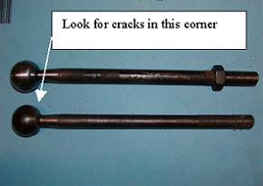 The tie rods bend at the ball end if the car is "kerbed" and should be tested for bends by rolling them along a table top. Severely bent tie rods (quite common) should not be straightened else you risk creating a fracture at the ball to shaft junction, which is often badly machined from new. As a minimum, look at this area with a hand-magnifying lens, but ideally, any suspect tie rods should be crack tested. These tie rods have rolled threads so don't be tempted to shorten & re-thread them to fit them into another car.
The tie rods should be shimmed before being connected to the rack shaft (item 36 on drawing) . They need to be firm without tight spots as they are moved about. The nylon ball seats on the tie rods (item 25) can be successfully re-seated with valve lapping paste but new seats are cheap & should be fitted in any rebuild. The metal versions are generally badly worn and when tightened by shimming, they become very "notchy" and they cannot pass the smooth rotation test mentioned above. The shimming is correct when the tie rod does not fall under its own weight, when the rack is horizontal, and without the anti-rattle spring fitted (item 24).
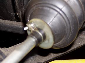 When refitting the rack bellows, the original wire clamps at the outer ends should be replaced with "zippy ties". If you want to keep the clips for originality sake, then use a plastic disc between the clip and the first bellows to stop the clip wearing thru the bellows. The Midget 1500 had this from new (see pic above).
Pinion end-float (in-out movement) must be imperceptible by hand , but at the same time, the rack must be able to be pulled through the pinion easily by hand. To get this right, the rack bodies & shaft must both be perfectly straight. Bent rack shafts and rack tubes are common!
All these racks were designed to be oil lubricated, not greased. Modern fluid or self-leveling greases such as Castrol SL appear to be an acceptable alternative.
Mods for competition
For those using their car for competition, some changes to the racks &/or positioning may prove useful. As discussed above, the location of the rack, its tie rod length & steering arm location all contribute to steering response. The base position must be selecting the correct length rack shaft to avoid bump steer. The most common change desired by racers is faster turn-in &/or more oversteer entering a corner. Both of these are achieved by altering the ackermann angle (ackermann is the lead one wheel has over the other when turning.....more ackermannn gives more toe out when turning , effectively pulling the car into the corner & giving more oversteer) . On a car with the rack at the front of the wheel centre (Sedan Spitfire etc), more ackermann is achieved by moving the rack rearwards &/or moving the steering arm closer to the disc. In most cases, a rack move of 10-15mm is adequate but experimentation is needed. On the saloon range, this usually requires the male spline on the column shaft to be shortened by about ½". TR's & Spitfires can accommodate this change with their original column adjustment systems. It is difficult on most Triumphs to bend the steering rod closer to the disc because of the ball on the rod end hits the disc, however a few mm often has a noticeable effect.
Substantial lowering of any Triumph will result in the steering tie rods working on (upward) angles they were not designed for. Unless the tie-rod angle is kept the same as original, unwanted toe-in on cornering &/or bump-steer, will occur.
On most models except the GT6 (where the rack will hit the sump), the rack can be packed upwards to correct this, but in extreme cases, the steering arm on the wheel hub has to be also heated & bent, definitely not being a job for amateurs. Longer U bolts to allow packing, can be taken from Marinas or Dolomites.
The photo below shows how bump steer is cured on a GT6 race car (note, this picture is with the car jacked up, hence the angle of the joint).
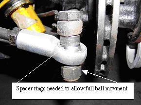 Another problem with both substantial lowering & requiring more negative camber for racing, is the lack of adjustment between the tie-rod end & the tie rod. What happens is the tie rod pulls out of the tie rod end when the alignment is done. Thankfully, by reviewing the table above, the owner can swap to a longer tie rod in many cases. With the saloon, you can fit the shortest TR inner tie-rod shaft, & place an extension piece in between this & the original tie rod end. Professional racers typically make extension pieces from threaded 4140 hex bar. Those with less facilities can cut off the threaded portion from an unwanted tie rod, cut off the threaded portion of an old tie rod end, & join them together with Loctite or similar.
The GT6 racer pictured above, used a T2000 tie rod to get matters right. Also note how a high strength ball joint is used to replace the conventional rod end. The "rose"or "heim" joint can either be fitted by boring out the tapered hole in the steering arm to accept a bolt, or making up a taper adaptor-the latter being common with US speedway vehicles. If you want to bore out the steering arm, be patient as they are very hard forged steel. The use of these joints requires small spacers above the "ball" so it does not jam on the bolt head or steering arm under rocking conditions (see picture).
The wider Midget 1500 or T2000 lock stops are a good conversion in Spitfires etc to prevent suspension uprights breaking from extreme full-lock cornering forces. In race applications the tight turning circle is not needed and this mod prevents horrific wheel reaction when steering control is lost. In particular, it stops the wheel spinning to an obscene angle if wheel control is lost in a big spin or when pushed off the track.
The 7 tooth Spitfire pinion gear can be used to reduce the number of turns from lock to lock in a saloon, but this extra tooth is really noticeable, making very heavy steering at parking speeds.
On all models, the notorious rack end bush can be changed for something more substantial by welding a larger tube into that area and using a big bush or even a bearing. The only downside is that a different rack gaiter is used.
© Terry O'Beirne TSOA Queensland


 In all cases, Triumph racks were made in both LHD & RHD formats, with the only difference being the handing of the casing & the pinion gear tooth angle—the rack shaft & tie rods remaining the same. With the exception of the Dolomites, 6 & 7 tooth pinions can be freely exchanged to give a quicker or slower rack as required. The 7-tooth (spitfire/TR) pinion is commonly found in race saloons.
 The tie rods bend at the ball end if the car is "kerbed" and should be tested for bends by rolling them along a table top. Severely bent tie rods (quite common) should not be straightened else you risk creating a fracture at the ball to shaft junction, which is often badly machined from new. As a minimum, look at this area with a hand-magnifying lens, but ideally, any suspect tie rods should be crack tested. These tie rods have rolled threads so don't be tempted to shorten & re-thread them to fit them into another car.
 When refitting the rack bellows, the original wire clamps at the outer ends should be replaced with "zippy ties". If you want to keep the clips for originality sake, then use a plastic disc between the clip and the first bellows to stop the clip wearing thru the bellows. The Midget 1500 had this from new (see pic above).
 Another problem with both substantial lowering & requiring more negative camber for racing, is the lack of adjustment between the tie-rod end & the tie rod. What happens is the tie rod pulls out of the tie rod end when the alignment is done. Thankfully, by reviewing the table above, the owner can swap to a longer tie rod in many cases. With the saloon, you can fit the shortest TR inner tie-rod shaft, & place an extension piece in between this & the original tie rod end. Professional racers typically make extension pieces from threaded 4140 hex bar. Those with less facilities can cut off the threaded portion from an unwanted tie rod, cut off the threaded portion of an old tie rod end, & join them together with Loctite or similar.
